Skip to content
3Shape Denture Design Step-by-Step
1.Order setup
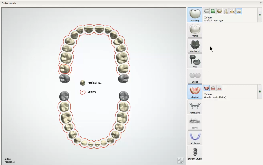
- Set up as artificial teeth and dentures gingiva.
- Choose a manufacturing process that is set up specifically for dentures. You can make a new one in control panel, choose cadoutputrawstl.dll, and make sure the ‘milling’ checkbox is left unchecked.
- Choose a gingiva type (injection molding or glued-in-teeth options) that determines the shape of the denture base. See Manufacturing Output for details.
- Optionally you can bridge together different teeth to create tooth blocks that you can mill or print yourself (if using this feature do not use ‘Injection Molding’ gingiva type).
- Option for denture predesign scan (if copying the denture design from the try-in).
2. Scanning
- Upper and lower arch scans are much the same as other indications but no annotations or green highlight needed.
- Wax rim step is required but it does not have to be an actual wax rim. It is preferred since the wax rims will tell us exactly where the occlusal plane is supposed to be in design.
- Final scan file must be a fully closed shape. To make sure it closes properly, do not trim the scan data. If the trimmed edge is higher than the deepest part of the palate, it will cut through that section in order to close the scan. Impressions and intra-oral scanning now supported in the 2018 version of 3Shape.
3. Design
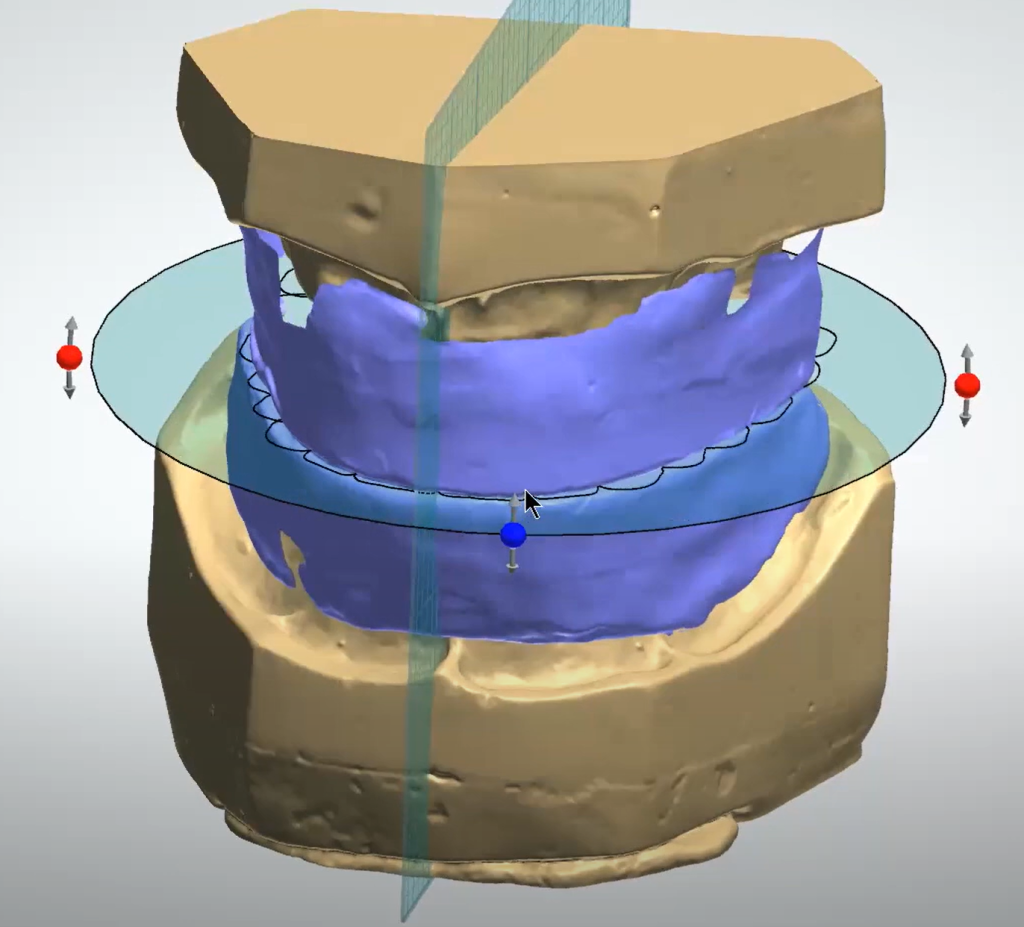
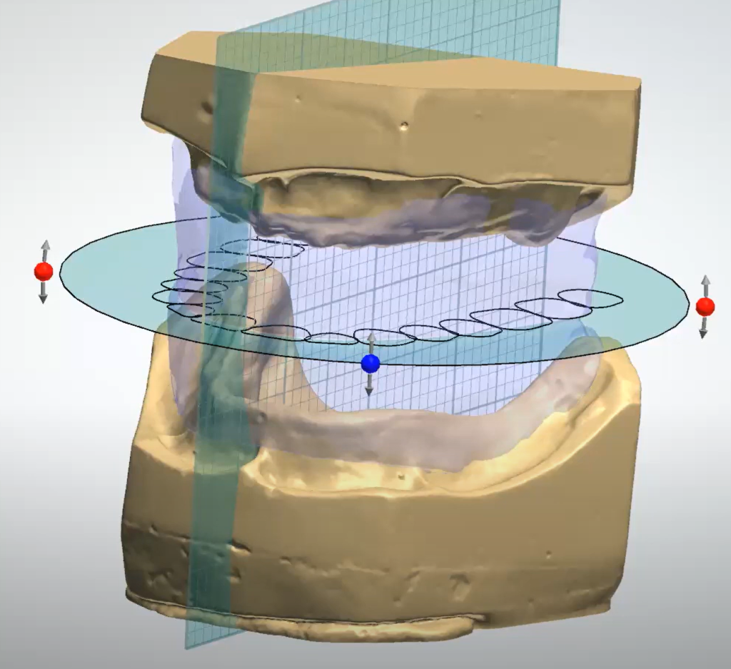
- Mark occlusal plane on wax rim by clicking 3 points then adjust the tooth chart as needed. If they did not scan an actual wax rim, mark 3 points anywhere then manually adjust tooth chart into position.
- Mark anatomic points on gingiva. Patient left or right-hand side can be marked as #1 or #2 but stay consistent once you’ve marked as one or the other. Points do not need to be placed perfectly as they are just used to determine the default library size.
- Adjust insertion direction as needed. By default, it will not block out undercuts, so any left behind will be extra retention.
- Add any extra blockout using wax knife tools. Typically, only needed for severe undercuts.
- Draw edge of the gingiva on the models.
4. Smile Composer Step
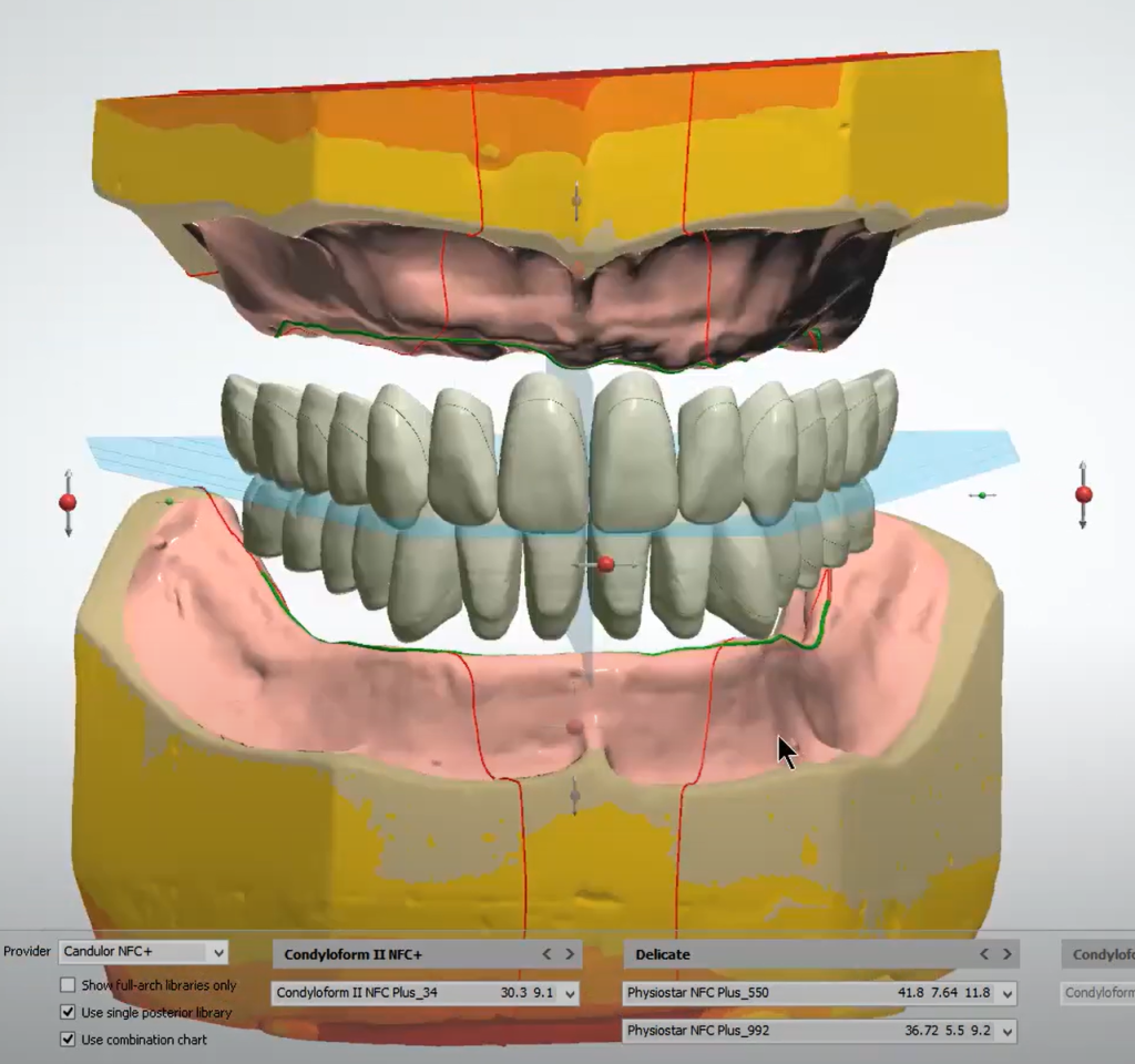
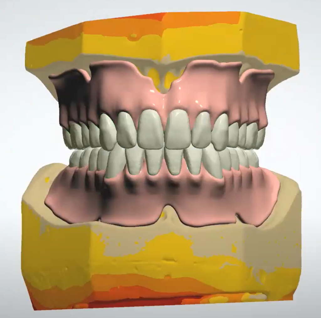
- Choose desired library and pick between a few anterior and posterior options. By default, only Candulor NFC+ is available, but more are available if they are downloaded during install, or if provided by other manufacturers. Occlusal plane tool is used to move entire set of teeth using transformation tools.
- Arch setup tool moves teeth in different groups by holding shift or ctrl and other teeth adapt to the new position.
- Individual setup tool can move units one at a time. The purple dot lets you pivot the crown around the opposing contact point. Right-clicking teeth will give you automatic ‘move to’ command to bring units into midline/mesial/distal/antagonist contact.
- Show Collision Details visual slider will show checkmarks if there are no collisions for each tooth and an exclamation mark for various collisions (A, M, and D for Antagonist, Mesial or Distal contact). This tool does not check if there is open contact.
- Morphing tool will be available only if tooth blocks were set up in the order form. Otherwise, the shapes of these teeth cannot be changed, only moved.
- Adjust gingiva edge, if needed, to make the denture base edge.
- If tooth blocks were set up in order form, there will be a finalize step where you can modify the combined bridge shapes.
- Sculpt the denture base with morphing and wax knife tools.
- Postprocess settings like glue spacer and minimum thickness. At this stage you can see which gingiva type option was chosen but you cannot change it.
5. Manufacturing Output
- A Manufacturing process should be set up with the ‘milling’ checkbox left unchecked, even if the lab does plan on milling. If it is checked then some of the below options output several unclosed stl files, which our mills and printers cannot use.
- STL files are generated differently based on the Gingiva Type options from the order form.
- Injection Molding generates one STL that includes the denture base and teeth as one file meant for milling or printing. This is what could be used as a denture try-in.
- Glued in Teeth (CoM), (Matrix), and (Arch) generate a closed STL file for the denture base. This format maintains a minimum thickness which means that if the denture teeth are placed too low they will not fit into the socket without some manual adjustment to the teeth. These are the main options that we can mill or print.
- Glued in Teeth (Basal Reduction) or (Manual Reduction) generates the same way as the other Glued in Teeth options except the sockets allow the base to go below minimum thickness, creating holes. This allows the lab to glue the teeth in before grinding away at the exposed underside.
- All the glued in teeth options may also generate different STL files for the teeth designs as well, but only if this is also purchased from the library manufacturer. If this is not purchased there will be a warning when generating STLs saying that creating the teeth STLs is not possible. It will still generate the STL files for the denture base despite this warning.
